
Beverage Bottling Factory Layout Checklist
A factory layout checklist for beverage bottling lines, covering process flow, utilities, conveyors, packing area, warehouse and installation planning.
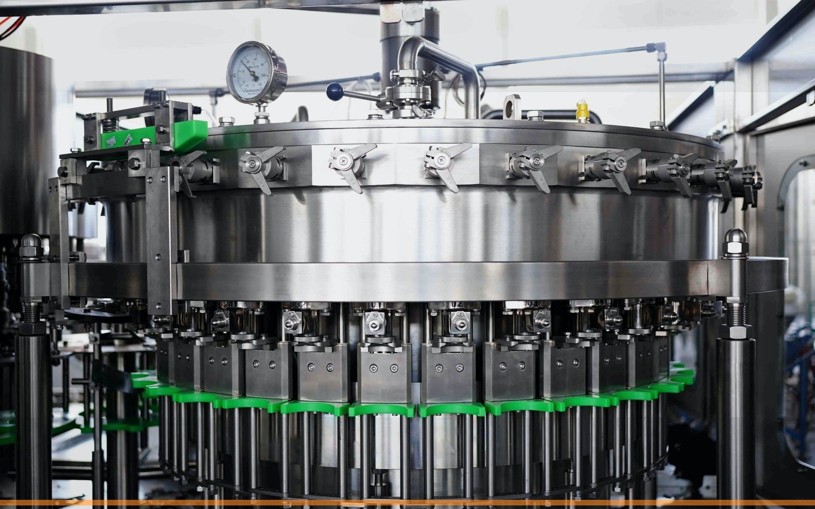
A good layout saves money after installation
Factory layout affects installation speed, operator movement, maintenance access, product flow and future expansion. Before buying a beverage bottling line, the buyer should prepare a simple floor plan with room dimensions, entrance size, ceiling height, drain locations, power points and warehouse area.
Plan the process flow from raw material to finished packs
A beverage factory usually moves from raw material or water treatment to processing, bottle blowing or bottle supply, filling, labeling, coding, packing, palletizing and finished goods storage. If the route crosses itself too many times, operators lose time and the factory becomes harder to keep clean.
Utilities and maintenance space
Machines need power, water, compressed air, steam or heat source, drainage and sometimes chilled water. Maintenance space around the filling machine, labeler, packing machine and control cabinets should not be ignored. Many layout problems happen because the machine can fit on paper but cannot be serviced properly.
Floor-space example: why machine area is not factory area
Hypothetical planning example: a proposed equipment block occupies 8.0 m by 2.5 m, or 20 m2. Suppose the supplier’s preliminary access drawing adds 1.0 m on each long side and 1.5 m at each end. Its rectangular working envelope is then (8.0 + 1.5 + 1.5) x (2.5 + 1.0 + 1.0) = 49.5 m2.
Those assumed clearances are not recommended safety distances. Actual distances must come from approved equipment access drawings and local requirements. The 49.5 m2 figure still excludes raw materials, finished pallets, utilities, cleaning facilities, segregation, building columns and circulation outside the envelope. It is not a factory-size quotation.
| Question | Evidence to request | Who confirms it? |
|---|---|---|
| Can the equipment enter? | Shipping dimensions, weights, lift points, unloading area, doorway and turning-path survey | Equipment supplier and qualified local rigging contractor |
| Can it run and be maintained? | Approved arrangement with opened guards, electrical access, part-removal paths and utility connection points | Equipment supplier, site engineering and operating team |
| Can the whole factory work? | Material routes, storage, hygienic zones, cleaning, waste, people, emergency access and planned expansion | Site project team with appropriate local specialists |
Use a drawing issue list before fixing the installation date
Give each drawing a revision, equipment scope and approval owner. Record an issue, the affected interface, who must answer it and the stage by which it must close. For example, an unconfirmed packer discharge height affects the conveyor interface; an unknown incoming air flow affects the filling-line utility schedule. Neither should disappear into a generic “installation included” statement.
Separate supplier-factory checks from site work. Use the FAT test record before shipment, then verify installed connections and integrated output against the agreed SAT checklist. An approved layout is evidence of coordinated planning, not proof that the line has passed acceptance.
Three approvals before the equipment ships
A machine outline is not an installation plan. Approve the access drawing, utility schedule and responsibility list together, using the same equipment revision and production format.
Access and service space
Measure the unloading route, door opening, turning space and ceiling obstructions. Add guard-door movement, cabinet access and component-removal space to the supplier drawing. A machine that fits the room may still be impossible to bring in or maintain.
Utilities at the connection point
For every module record voltage, phase, frequency, connected load, operating and peak demand, pressure, flow and utility quality. Separate PET blowing air from control air. Confirm whether cleaning and production can overlap; a compressor nameplate is not a measurement at the filler.
Named installation owners
Assign unloading, local piping and cabling, drains, testing, operator training and open-item closure. Agree who supplies each item and what proves completion before booking travel or promising a production start.
Planning guidance only. Supplier-approved drawings and qualified local engineering determine structural loads, lifting, electrical protection, hygienic design and safe clearances.
Is there a universal floor area for a 5,000 BPH line?
No. The package, blowing or bottle supply, treatment, packing method, storage and service access change the space requirement. Compare layouts at the same scope, not only at the same speed.
What should be ready before site acceptance testing?
Document utilities under operating load, completed safety checks, trained operators and enough production materials for the agreed run. Close critical installation issues before measuring accepted output.
How Allot Tech uses layout information
Allot Tech uses layout information to check whether the proposed line is practical for the buyer. We can discuss machine sequence, conveyor direction, operator position, packing area and export shipment planning before the buyer commits to equipment.
Buyer checklist before requesting a quotation
- Factory length, width and height
- Door and container unloading access
- Water, power and air supply
- Drainage and clean zones
- Packing and warehouse area
- Future expansion route
Continue planning your beverage machinery project
Use these internal pages to compare equipment scope, line configuration and export support before requesting a final quotation.
Common Questions About beverage bottling factory layout
When should factory layout be discussed?
Layout should be discussed before confirming the final machine list, because conveyor length, machine direction and packing area affect the quotation.
Can Allot Tech help review a simple factory drawing?
Yes. A hand sketch with dimensions is already useful for early discussion.
Why leave extra maintenance space?
Operators need access for cleaning, inspection, spare parts replacement and safe operation. A cramped layout can slow production.
Need a practical quotation from China?
Allot Tech (Suzhou) Co., Ltd. can help match process, filling, labeling, packing and export support for your beverage project.
Contact Allot TechPut every connection and maintenance route on the layout
A layout should show more than machine rectangles. It should connect raw materials, treatment, filling, packing, people, waste and finished goods while reserving safe access for cleaning, change parts, maintenance and future capacity.
| Utility or space | Information to confirm | Layout consequence |
|---|---|---|
| Electrical | Voltage, frequency, phase, connected load, panels and isolation | Cable routes, panel access and distribution capacity |
| Compressed air | Pressure, normal and peak flow, quality and receiver location | Pipe size, dryer or filtration and pressure-drop control |
| Process and cleaning water | Quality, pressure, flow, temperature and storage | Tanks, pumps, hygienic piping and cleaning stations |
| Drainage | Expected flow, chemistry, floor slope and treatment | Drain positions, safe cleaning and wastewater route |
| Cooling or heat | Chilled water, cooling water, steam or thermal demand where applicable | Utility room, insulated routes and service access |
| Material flow | Preforms or bottles, caps, labels, film, cartons and pallets | Storage, staging, forklift routes and finished-goods exit |
Draw access envelopes
- Guard and cabinet door opening
- Filler bowl, mold or change-part removal
- Operator standing and replenishment points
- Maintenance lifting and spare-parts routes
- Emergency exits and safe crossing points
- Space for a future machine or conveyor extension
Issue one coordinated drawing
Use supplier general-arrangement drawings and one site master plan. Mark utility connection points, elevations, conveyor direction, column positions and approval revision so civil, electrical and mechanical teams work from the same basis.
Buyer questions
What utilities should appear on a bottling-line layout?
Show electrical supply, clean and instrument air where needed, process and cleaning water, drainage, cooling or chilled water, steam or heat when applicable, ventilation and utility connection points.
How much maintenance space should be left around machines?
There is no universal distance. Use supplier access drawings and allow room for doors, guards, mold or change-part removal, platforms, lifting, cleaning, spare-parts movement and safe operator routes.